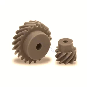
Helical Gear
Helical gears are quieter and operate more efficiently than spur gears. The teeth of a helical gear are cut at an angle to the gear face so that they gradually mesh as the gear rotates. The tangent to the helix angle varies in proportion to the thrust load. A helical gear is an excellent choice for high thrust because it produces far less friction and requires fewer bearings.

Get In Touch
We have exported our products to clients worldwide and earned a good reputation because of our superior product quality and after-sales service. We warmly welcome customers both at home and abroad to contact us to negotiate business, exchange information, and cooperate with us.
Website
About helical gears
A helical gear doesn’t have a single best pressure angle, but it does have a center play. Helical gears have a smaller cross section, which affects the radius of curvature and normal force. As the helix angle increases, the contact ratio decreases. This reduces the contact ratio and increases the length of the gear contact line. However, the effect of this reduction is proportional to the helix angle.
In addition to higher load capacity, helical gears are quieter and have less friction than spur gears. Since helical gears mesh in small increments, they are better suited for large loads and are also more efficient in high speed and high load applications. They are also a good choice for conveyor belts and elevators, and they can be used with parallel or non-parallel shafts.
Helical Gear Geometry
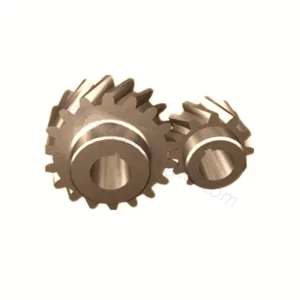
Helical gears have two essential characteristics: axial excitation force and circumferentially curved contact planes. The linear motion equation determines the axial excitation force in the rotational direction with a damping coefficient of 0.07. In the helical gear, the bearing stiffness is 6.84 x 10⁷ N/m, while the plate damping is 2,040 kg/m2s. The profile of the gear body is modeled by a mathematical model used to calculate the kinematics of the gear. Helical gears are similar to spur gears; the only difference is that the teeth are cut at an angle to the axis. Because of this, the contact line between the two teeth is not parallel to the axis, and the teeth gradually mesh, making the gear run smoothly. Helical gears can mesh in one of two ways. In one method, the shafts are oriented at the sum of the helix angles; in the other case, the shafts are oriented at different helix angles.
The root stress of helical gears is different from that of spur gears. The rim deformation of thin-sided helical gears is more significant than solid helical gears. To calculate the root stress of a helical gear, it is necessary to determine the rim and web thickness, the rim and web helix angle, and the effect of the helix angle. The results obtained from this method can be used to design suitable helical gears for any application. The helical gear can have a symmetrical shape, allowing rotational movement. Its tangent lengths are proportional, and the radial radii are similar. It is essential to measure the base tangent length for the most accurate measurement. Helical gears may have a different shape than spur gears. However, a helical gear can have the same radius as a spur gear, which means less radial force.
Products Center
What types of helical gears are there?
Helical gears are available in two teeth configurations: left-handed and right-hand. Helical gears transmit energy through two axial compositions: parallel and perpendicular.

axial configurations!
Mounting Specifications
Keyway
One or more square cutouts exist in the gear bore for exact mounting on the shaft.
Split
The hub is split into several pieces that are tightened down by a separate clamp to grip the shaft.
Set Screw
The gear is attached to the shaft by screws through the hub.
Simple Bore
A straight bore designed for adhesive attachment.
Hub Clamping Screws
The gear is attached with a screw that squeezes the inner diameter of the hub to a tight fit around the shaft.
Basic Parameters for Gear Design:
Helical Gear Accessories
Due to the gradient of the gear teeth and the pressure applied to the teeth, helical gears are prone to misalignment by axial thrust. This can be remedied by the use of thrust bearings and high-pressure lubricant. If the operation cannot use thrust bearings, herringbone gears may be an alternative.
Helical Gears Manufacturing
Manufacturing Method
Materials
Pricing
1. The size of material required determines raw material costs
2. Plus estimated machine and gear-cutting time
3. Plus heat treatment costs (only if required)
Applications Of Helical Gear
Most of the reputable Industrial Gearbox Suppliers suggest helical gears work under heavy load efficiency and of course when we need silent operation such as in automotive applications.
- Fertilizer industries, printing industries, and earth-moving industries
- Steel, rolling mills, power, and port industries
- Textile industries, plastic industries, food industries, conveyors, elevators, blowers, compressors, oil industries & cutters.
In addition to the above applications, there are many others. The overall application of helical gears and helical gearboxes is widespread. Keep an eye on the space to know more.
Frequently Asked Questions
What are the advantages of helical gears?
Its Advantages:-
- The angled teeth engage more gradually than spur gear teeth so that they can run more smoothly.
- Helical gears, as well as helical gearboxes, are highly durable and ideal for high-load applications.
- It can transmit motion and power between either parallel or suitable angle shafts.
Why are helical gears preferred for heavy load applications?
Which is better: spur or helical gear?
Spur gears have flat surfaces that fit into matching holes in adjacent components to form a joint. Spur gears can only change the direction of rotation by 90 degrees, so they cannot be used on parts that are perpendicular to each other. However, they are preferred over helical gears because they allow for easier assembly and less wear on the components.
What is the thrust in single-helical gear?
Why is there a gap in the double-helical gear?
What are the potential applications for helical gears?
Helical gears are good solutions if you’re concerned about the speed of your machine, the noise it emits, or the amount of vibration produced by its function. If you’re interested in cutting new helical gears for your next project, contact us!
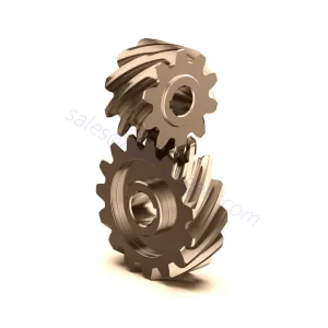
Double Helical Gear
Double helical gears are a variation of helical gears in which two helical faces are placed next to each other with a gap separating them. Each face has identical, but opposite, helix angles. Employing a double helical set of gears eliminates thrust loads and offers the possibility of even greater tooth overlap and smoother operation. Like the helical gear, double helical gears are commonly used in enclosed gear drives.
Helical gears are the default choice for heavy-duty machines and construction operations. They are available in various specifications and sizes. They come in 16, 12, 10, 8 and 6 transverse diamter pitches. They are manufactured with 14 1/2deg normal pressure angle and 45deg helix angle. Other features of these gears include hubs, finished bore and heat-treated teeth. These are available for a wide range of applications, including traction and abrasive applications. Some of the common materials for helical gears are steel and stainless steel.
When considering the design of helical gears, keep in mind that they have different center distance values from spur gears. These differences mean that the allowable tangential force in the center of the gear must be determined based on a particular application environment. The values for surface durability and bending strength were calculated based on specific application conditions, but the user should use them in their own calculations. And if there is a need for more robust gears, helical gears can overcome these limitations with double helical gears.